Allow me to give you a bit of insight why not to come and why you need to come:
Why not to come:
Having a couple of days off work and off family and infatuating yourselves with the ample social offerings – Wrong
Why to come:
Diving into a (steep) learning experience and take this home/work/play – Right
A comment from the observer:
The program has been carefully hand-picked and adjusted to maximize the learning experience for the delegates. It is not for the faint hearted but for all in our community who thrive on pushing the agenda hard. And there is an agenda to push: CO2, circularity, inflation and the money market as such…
The BILT team is trying very hard to give you answers.
A few stats about Riga:
Riga is the capital and largest city of Latvia, a country located in the Baltic region of Northern Europe. Here are some key points about Riga:
Location: Riga is situated on the Gulf of Riga, at the mouth of the Daugava River, which flows into the Baltic Sea.
History: Riga has a rich history dating back more than 800 years. It was founded in 1201 by the German bishop Albert of Riga and has since been influenced by various cultures, including German, Swedish, Polish, and Russian.
Architecture: The city boasts a diverse architectural landscape, with influences from different periods, including medieval, Gothic, Renaissance, Baroque, and Art Nouveau styles. The historic center of Riga, known as the Old Town, is a UNESCO World Heritage Site and is famous for its well-preserved medieval buildings.
Culture: Riga is known for its vibrant cultural scene, with numerous theaters, museums, art galleries, and music venues. The city hosts various cultural events and festivals throughout the year, including the Riga Opera Festival, Riga City Festival, and the Riga International Film Festival.
Economy: Riga is the economic and financial center of Latvia, as well as the largest city in the Baltic states. The city’s economy is diverse, with industries such as finance, manufacturing, trade, logistics, and tourism playing significant roles.
Education: Riga is home to several universities and higher education institutions, including the University of Latvia, Riga Technical University, and the Art Academy of Latvia.
Transportation: Riga is well-connected by air, rail, road, and sea. Riga International Airport is the largest airport in the Baltic states and serves as a hub for air travel in the region. The city also has an extensive public transportation system, including buses, trams, and trolleybuses.
Tourism: Riga is a popular tourist destination, attracting visitors with its rich history, cultural heritage, and architectural landmarks. In addition to the Old Town, notable attractions include the Riga Central Market, Riga Cathedral, Freedom Monument, and the Latvian National Opera.
Overall, Riga is a dynamic and culturally rich city with a blend of historical charm and modern amenities, making it a fascinating destination to explore in Northern Europe.
It’s been a while – admittedly with Covid and all the other noise of 2020 going on we were busy to save – our skins, the company, you name it.
Changeover – 2020 bye bye – here comes 2021
2021 – fresh year – less noise on the TV regarding an American President, so we can focus on our real life things again.
Due to an unexpected hoopla I had to reinstall my workstation and – low and behold – we went into the other Autodesk offerings in our account and we found Fusion 360.
Nice little piece of soft – pretty cool to edit your STL files for sending it to the 3D printer.
And it comes with a desktop connector
I have all my Fusion files at hand – so – I thought, lets clean up, let me get rid of these little doggerels that claim cloud space (and probably Autodesk credits)…
But for the time being – Autodesk is owning my Fusion 360 designs – not that I have anything incriminating or embarrassing up there – but if you plan to choose Fusion 360 to model anything that might earn you Facebook presence… think twice…
The program in the spotlight this time is Vectorworks Architect from Vectorworks which is a Nemetschek Company. A BIM software that is oftentimes overlooked in favor of the bigger names in the industry but is this justified?
The Vectorworks program suite is split into 4 programs. Each caters to a specific design discipline and can be purchased separately or as the Vectorworks Designer Package which contains all features.
In the table below the main highlights of each program as shown on the website are displayed.
As my area of expertise does not extend to GIS and Stage Design we will stick to Vectorworks Architect during this evaluation which contains all the tools in FUNDAMENTALS and more.
These are my experiences in using the program over de last few days. Keep in mind this is from the perspective of someone who has never used this program before.
Interface
When you first open Vectorworks after getting the license setup you see the interface as shown in the image below, it’s quite overwhelming, and Tools are located in different locations depending on what you want to do.
Basic tools are located in the top left, these are your generic selection, move, mirror, and so on. Also included are the shape and polygon/line tools, Eyedropper, Selection, Visibility & Symbol tools/
Below that is the Toolbox containing the different toolsets which are based on which discipline of Vectorworks you are using, This is the Designer Package and as such we have access to all of the options. The buttons at the bottom allow you to switch between the different toolsets thereby showing the relevant tools in the list above. Here you will find almost all object creation tools a few exceptions of which are the roof and floor Tools. These can be found under the Designer tab next to File and Edit when selecting multiple walls.
Object manipulations such as creating voids and such can be accessed from the Modify tab at next to the View tab.
The bar above your viewport contains the visibility, layer, style and view navigation tools for the current view. Right below this are the tools and options for the currently selected tool. This is also where you can specify an object before placement.
To the right of the viewport is the Object Info panel which displays the information about the current object and allows you to edit the properties using the corresponding tabs in the menu.
Below the Object Info panel is the Navigation. This gives you a different project navigation option as well as being able to control visibility for each class and layer for the current view.
To access the report options you need to open the Tools tab located at the top of the window.
To conclude it is not the most consistent UI design with how tools are located and accessed but with enough usage, this won’t be a problem, proven by the many people that use Vectorworks daily.
Out of the Box Template
When first downloading Vectorworks you will get the option of choosing a few different configurations depending on which country you select. These configurations influence the language of the interface and the content libraries included with the package. In my case I was able to keep my interface in English while getting the content libraries and basic setup as required by the Dutch standards. This will also be what I will be basing my interpretation of the Template on.
The way the components are classified is according to the Class parameter which if I am correct correlates to the Assembly code and is exactly as would be required here, as such this requires no tweaking. All created elements are automatically set to the corresponding class and manual manipulation is possible if needed.
The included object libraries, as well as generation-presets, are more than enough to be set up for most projects without having to do any tweaking. Most content is created by generation using adjustable parametric objects, as such most desired results can be created with a few quick edits and can then be saved as a preset for future use.
The included libraries also include a lot of manufacturer specific content for some of the big suppliers in the Netherlands, I expect this to be the same depending on which country you select during download but I have not tested this.
Overall this is one of the most complete template experiences I’ve seen so far and pretty much everything you need is included out of the box.
Vectorworks Libraries
Modeling
Modeling in Vectorworks requires a basic understanding of the way Vectorworks divides up the project space which is why we will cover them quite thoroughly.
Design layers & Stories
Vectorworks uses two systems to divide up the project space. Both offer similar functionality but in different ways. There is the original Design layers system which is included in every Vectorworks software package and the Stories system which is included with Architecture in addition to Design layers.
Design Layers
Stories
The design layers act as a mix between levels, groups, and views, they are groups of objects of which the visibility and editability can be controlled. They also work like slices of the model where manipulating the stacking order determines the position of a slice in a view. You can also give them an elevation which sets the default placement height of objects which is why I mentioned they are a mix between levels and groups. In addition, there is a parameter to set the layer wall height which sets the default height of height constrained objects placed on this layer if the object in question was set to extend to the layer wall height instead of stories. Talking about stories you can link a story to a design layer as you can see in the image above.
So now we have design layers that act as levels and views what are stories for? Well, Stories are the actual building levels within a project. they can like Design layers be given an elevation but in addition, as shown in the image above you can specify sublevels based on the main story with a specified offset. These sublevels can then be automatically referenced by objects to extend to certain sublevels for automated placement. This can be done in the Styles settings of each object which is Vectorworks rendition of Revit Types.
While working with this system I have gotten used to the way it works but I can’t say I prefer it compared to a more generic level and view-based system. I find both systems in Vectorworks offer similar features and would find it more intuitive if they were incorporated into one system but this is just my personal opinion.
Styles (Object definitions & Generation)
In Vectorworks Styles are the parameters and settings which define a series of objects these styles can look very different depending on which type of object is selected or being created. This is due to the fact that some of the Vectorworks content is based on generation.
One of the cool things you will notice while editing a wall style or working with walls or layered objects is that each layer is treated as a separate object and can be modified individually. In the picture below the styles settings for one of the components making up a wall are shown. Here you can see that the top and bottom of the components can be defined relative to the wall or by the aforementioned stories and that a positive or negative offset can be given, this means that you no longer need to place separate walls to be able to individually control separate parts of a wall. This small addition adds a ton of functionality in my opinion.
These layered styles can be applied to any layered object and created in much the same way as you would in most BIM software, a nice thing though is that Vectorworks includes a lot of wall styles related to your working local which saves you the time to set them up.
Generation
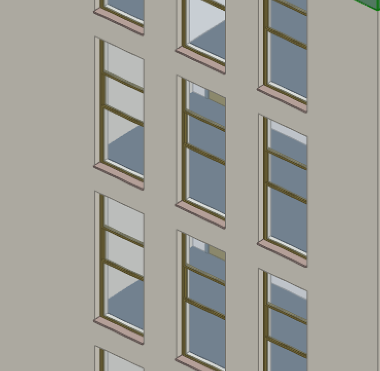
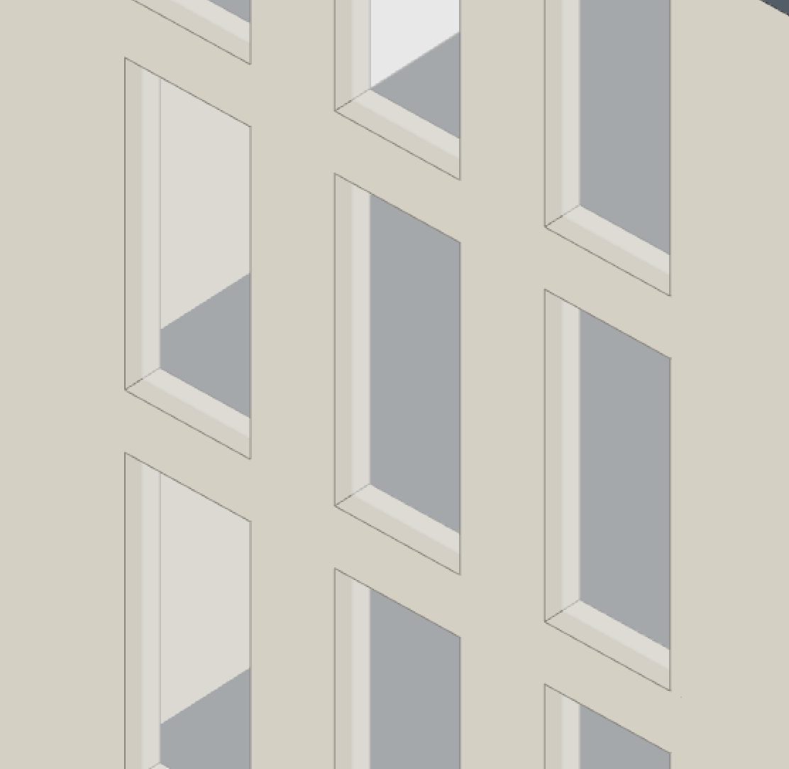
I mentioned generation before and Vectorworks makes a lot of use of it to its advantage. For example, the joinery tool which can be used for windows and doors. Using this tool you can generate almost any window or door layout, either by using a template as shown in the image below or defining it yourself from scratch. The tool covers many aspects of creation from handles to vents and shades and is relatively easy to use.
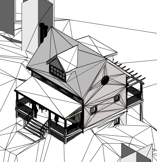
Another tool where generation plays a big part is the roof tool. as previously stated this can be accessed under the Designer tab after selecting one or more walls or a polygon, Vectorworks uses polygon edges or wall objects to create a roof using generation, when using the tool you are greeted with the menu as shown bellow
Generation Menu
Face Edit Menu
This menu allows you to specify the way the roof initially generates, which style is used, and the parameters it uses to do the generation, of these parameters one is always calculated based on the others, you can pick the calculated value by using the bullets.
After the initial generation, it is then possible to edit the shape of the roof using one of the blue nodes that appear on each roof race on selection, this menu is shown above.
Another very cool generative feature that is included is the automatic dormer generation by placing a 3D symbol of a window on the roof face thereby launching the dormer generation tool which allows you to specify its geometry and styling.
While being quite different from the competition Vectorwork’s implementation of a roof tool is quite powerful for creating complex roof structures in a short amount of time and quickly editing them when needed.
Elevators & Escalators & Stairs
Vectorworks also includes a tool to generate elevators and escalators which I have not seen included in another software before, which is really useful.
The built-in stair tool is also easy to use and has extensive functionality which results in good-looking and accurate stairs according to your specified parameters.
Conclusion
The other tools like walls, beams, etc. all work as you would expect using the previously mentioned stories and layer settings. If you combine that with the nice features previously mentioned I would say Vectorworks is a very capable program for your modeling needs.
There are however some features which are missing or could use improvement in my opinion such as
There is no dedicated foundation tool, you have to use walls or floors
Some aspects of tools are not always clear
A few extra features on tools especially roofs seem broken or are missing extra positioning options that would make them useful
The fascia tool only works for the horizontal edges of roofs.
Content Creation
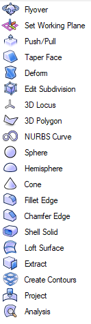
Content creation seems to be mostly done by using the included freeform 3D modeling tools. These are similar to other Push/Pull modeling software’s like Sketchup, Rhino, and FormIt, with more or fewer tools than you would be used to depending on what you use, see the image to the right for the toolset.
These created elements can then be assigned data and saved as a 2D or 3D symbol which is Vectorworks version of a saved object definition.
There does not seem to be something like a family creator like is available in Revit for parametric manipulation and this feature does seems to be missing in Vectorworks.
It does however seem possible to create, but not manipulate objects based on parameters by using Vectorworks built-in visual scripting engine Marionette
Plan Presentation
Vectorworks out of the box produces very clean and readable plans and with tweaking is able to create some of the nicest colored elevations and 3D views I have seen without leaving the software or rendering. Annotations are also straightforward and work as expected in addition to very clean tags for objects that make for a clean plan overall.
Reporting
Vectorworks also has some very capable reporting capabilities. apart from the usual quantity takeoffs and scheduling they also include cabinet and window schedules which is a really amazing feature that I have yet to see in another software. see the picture below, this will save a lot of time for people that need to create these schedules via other means normaly.
IFC Import
The IFC capabilities of Vectorworks seem capable, as a test I have exported the basic sample project from Revit to IFC 2×3 and imported it into Vectorworks. The material, properties, and geometry information is imported perfectly, there are however some parts that are slightly bugged.
Curtain walls are imported as Windows and a group, upon ungrouping object information is lost.
But apart from this bug, the import process seems to work well, see the result in the image below.
IFC/Revit Export
When exporting to IFC there are few options apart from the basic IFC versions selection of which it supports 2×2, 2×3, and 4, Some project settings, and which design layers to export. The IFC mapping is actually done on a per-object or per style basis in the data tab of that object’s properties.
As a test I exported a test project from Vectorworks to IFC 2×3 opened this in an IFC viewer and Imported it into Revit and also linked into Revit.
Vectorworks
IFC Viewer
Revit Import
Revit Link
As you can see from the results this was not the most flawless export, While the IFC file itself seems to be great without artefacts or glitches it seems that Revit specifically does not like the way the IFC is structured as on either the import or the link there are either large bits missing or artefacts.
As an additional test, I imported the Vectorworks IFC into Renga (See our previous post), while an improvement it still has artifacts like missing a few of the roofs, see the image below. A unique feature Vectorworks has is that it is the only software as far as I know that supports an RVT export so maybe this gives a better result, but as you can see in the image below the geometry does come over perfectly however everything is a generic model and the information contained is lost.
To conclude I would stick to linking IFC’s created from Vectorworks based on these results but you might get different results so its always worth a try.
Renga Import
Vectorworks RVT Export
Rendering & Presentation
Vectorworks has quite a few ways of presenting projects. Either via the integrated Renderworks render engine which gives very clean and fast results, or by using the live link with Lumion if you happen to use that. or exporting your project into one of the many file formats that Vectorworks supports and rendering in any software of your choosing be it Blender, Unreal Engine, Cinema4D, Maya or 3ds Max.
Another option is to create a virtual tour using the built-in cloud presentation settings or going into Augmented reality using the Vectorworks Nomad app to make design decisions.
In addition to these options, there are also image manipulation tools included where you can tweak images with a number of filters and sliders.
By having all these options I think Vectorworks has got a good mix of ways to present projects to clients and the capabilities to do so at a professional level. Sadly it does not support Enscape as of yet.
Stability
During my testing of Vectorworks I encountered numerous small hiccups and stutters using the software, nothing that bad but enough to not be a smooth experience, these happen mostly while panning, zooming, or editing the model your experience may vary but this is what happened to me.
In addition to those stutters I have also experienced three crashes upon which all work since the previous save was lost, this is something to take into account and a lesson that saving frequently is extra important while working with Vectorworks.
Learning Curve & Support
From my experience, over the last few days, Vectorworks can be quite overwhelming but the provided tutorials are enough to get you going but don’t have the necessary depth to fully understand the finer parts of the program. In addition, many UI’s of tools have changed drastically over the years so finding the correct learning material to know how something works can sometimes be difficult but this is a good sign that improvements are still being made each year.
Price
As mentioned before Vectorworks is available in 4 sub packages and 1 all inclusive suite. So how does the Architectural package compare to the competition.
PROGRAM
Vectorworks Architect
ArchiCAD
Revit
Yearly Price
€1.390
–
€3195
Perpetual License
€2750
€5520
–
As you can see from the table Vectorworks is quite a bit cheaper than the direct competition. One thing to note is that during my evaluation period I got quite few offers for extra discounts so the price you might be paying could be even lower.
For recently graduated students they also offer a 40% discount under their student2PRO program which might make the software extra appealing to students just starting out.
Conclusion
Coming back to the question at the start of this article, Vectorworks is often overlooked, but is this justified?
Based on my experiences while using Vectorworks, looking at the features and capabilities it has i think it should be seriously considered as an alternative. Especially the well filled content libraries based on your local, that require little to no setup make it a good software to facilitate the transition from 2D to 3D, since most of your time will be spent actually working instead of creating content to get your work done.
Now it might not be the most stable and smoothest running software, also the UI seems a bit chaotic with how tools are placed but take into consideration that its only 1/3 to 1/2 of the price of the two big competitors while only offering slightly less functionality.
These reasons make it a perfectly reasonable alternative to Revit or ArchiCAD and definitely not one to be underestimated but one to consider.
The program in the spotlight this time is Renga from Renga Software in Russia.
The software has several features according to their website:
Architectural Design
Structural Design
MEP Design
Scheduling
These are my experiences in using the program over de last two days. Keep in mind this is from the perspective of someone who has never used this program before. And focusing mostly on the architectural aspect of the software.
Interface
When you first start Renga you are greeted with a very clean interface as you can see in the image below. This theme is continued throughout the software with consistent menu placement and interaction which is nice to have.
When starting a new project, you are again greeted with a clean minimalist interface as shown in the image below, gone are the big sidebars that you know if your coming from Revit. Now all you have is a small rectangular menu containing all your tools at the top right that expands downward as needed (a thing to note is that on a 1080p display at 100% scaling I have never had to scroll in this menu as of yet) and a bar at the top center which has your generic save, open, undo and export buttons, etc. This is also where you access the project-wide settings and your object libraries.
Now you might be wondering where is the project browser? Well at the very top of the window there is a tab with the current view and a + sign next to it. This is the project browser, you open it by pressing the + sign that lets you open any view from the project and have it as a new tab next to your current view. So, a very different approach compared to the competition but not necessarily a bad one.
Modeling
Modeling is straightforward for the most part and like other programs, select your wall, constraints, and go at it. Where things change is that modeling and manipulation of objects mostly work with nodes. This manipulation went as you would expect, all the basic functions that you would want are available and work great, Copy, mirror, array (radial & linear), etc.
Now making windows and doors is done in a very cool way. You place the window opening that you can define the height and width of and the way it is shaped so round, angled, etc.
Inside this opening, you can use a configurator to generate a layout which is used as a template to generate the window. This allows great flexibility in the quick creation of window and door objects. The only downside is that you can’t define the size of window partitions in dimensions but only with percentages. This same process is used for the creation of doors.
This means you might need to make a few variations depending on your project. In addition to this, there is also a cool function that windows wrap around walls. See the example below where one window spans three wall segments. This is also the reason why there is no curtainwall tool since the window and door tool both contain any functionality that would be inside a curtain wall tool.
Stairs and ramps are also fairly free of limitations in modeling which means you always get a stair that fits and just edit the run amount to get your desired riser height and tread depth which can be seen on the properties menu.
A nice convenience that I haven’t seen anywhere else is that walls auto attach to a roof if they are cut by the geometry of the roof.
When it comes to materials, they easy to set up and apply to elements based on a layered material construction that has been made. One thing to consider is that this works on a layering system with one material being the core with a variable thickness, this thickness is calculated based on the thickness of the element and subtracting the other layers. To add to this there are no element types in the way other programs use these, every element is an instance which might be a problem in larger projects when project-wide changes need to be done.
But apart from all this good stuff some parts are less well developed.
The railing tool only has one geometry type and only the height and distance between posts are editable,
Stair railings and normal railings don’t join together.
The Railing always extends by about 20cm which cant be edited and needs to be taken into account during modeling.
There are no temporary dimensions, This means drawing a lot of temporary lines or grids to position objects correctly,
Apart from the windows & doors, no object seems to wall aware which also results in a lot of manual positioning.
There is very limited or no functionality for detailed elements like gutters etc.
There a no site tools or ways to add topo surface as far as I have discovered.
Content Creation
One of the strange things about Renga is that there is no Freeform modeling environment. All assets are generic scalable models, Some of the MEP families do have specific geometry editing but most contend is a scalable OBJ file, this means that to add new content you can just grab any OBJ file from the internet and use it in your project and define its properties. This gives you access to a high variety of high-quality content but these are not fully parametric on the properties side in addition to having little control over visual properties.
Out of the Box Template
The base template is almost empty which can be a good thing, but this means as a new user you need to first add a lot of stuff to make it useful for your purposes. But adding content is easy and straightforward so this should not be a big problem.
Plan presentation
Presentation is straightforward, clean, and decently automated due to the use of view templates and filters which can be easily applied and edited to suit needs, This in combination with being able to re-add the dimensions and grids placed in the work views on the presentations views with the click of a button makes this a fairly fast process. It has a few quirks to get used to but it is perfectly fine for what it needs to do.
IFC Import
The IFC capabilities of Renga seem capable, as a test I have exported the basic sample project from Revit to IFC 2×3 and imported it into Renga. The material, properties, and geometry information is imported perfectly, there are however some parts that are slightly bugged.
The glass materials are not properly recognized as glass and thus show up opaque
The RPC Site trees are distorted and show up strangely.
But apart from these two bugs, the import process seems to work well, see the result in the image below.
IFC Export
When exporting to IFC there are not many options, while you can create property sets for each model category in the interface there is no option to select which ones are exported. This only leaves exporting all the property sets. Another limitation is that the only export option is IFC 4. This means interoperability with programs that don’t support this is limited or must happen via an indirect process by downgrading the IFC model.
As a test, I have exported a test project from Renga to IFC and then opened this in an IFC viewer and imported it into Revit.
The export from Renga just like the import seems to work well. The only thing missing from the export when opened in the IFC viewer is that the stair railings seem to not be exportable. This same bug is seen when you import the IFC into Revit but in addition to the railing problem, there are a few new problems.
Windows turn opaque possibly due to the way they are defined in Renga.
All the content geometry that is defined via an OBJ file in Renga as explained before is reverted to their original dimensions before scaling. This should be because Revit has some problems with importing IFC 4. This bug does make collaboration between a user using Renga and Revit difficult.
Model in Renga
Model in IFC Viewer
Model in Revit
Rendering
There does not seem to be any internal rendering engine but the 3D viewer does look great and can be used to present designs to clients. There does seem to be a partnership with the Artisan rendering program from PICTOREX Ltd but this has to be bought separately. As an alternative, there is also the option to export the model as an OBJ, DAE, or STL for rendering in an external program like Blender, Lumion, etc.
Price
Renga is available in 2 versions, Renga & Renga x3 but as of this writing, I have not been able to find out what the difference is due to the support center only being answered in Russian. But both versions are available in a variety of payment options. Take note that to upgrade the permanent license to a newer version there is a 450 USD upgrade fee.
Renga Version
Renga
Renga x3
Permanent license
1800 USD
4000 USD
Annual license
800 USD
2000 USD
Monthly license
80 USD
240 USD
Update package
450 USD
450 USD
Renga System Prices
These prices are considerably cheaper than some of the competition namely ArchiCAD or REVIT but it is also more expensive than Edificius that we took a look at last time while offering a better experience but most defiantly a lot less functionality for the price.
Conclusion
While there a few quirks here and there, the core is a solid piece of software with a clean interface that has all the functionality needed to get a project done and that is quite intuitive. This is delivered for a much lower price than the competition which makes it a compelling option for those with limited financial means that do want a solid experience.
The program in the spotlight this time is Edificius from ACCA Software in Italy, Europe. They offer multiple programs but today we are just looking specifically at this one.
Its a BIM software that promises to accomplish a number of things according to their website:
2D & 3D Architectural design
3D Interior design
Garden and Landscape design
MEP plant modeling
Job scheduling
Dynamic cost estimation
Rendering
VR – Virtual Reality
Video editing
Online model viewing
These are my experiences in using the program over de last two days. Keep in mind this is from the perspective of someone who has never used this program before.
Interface
One of the first things you notice if you start it up is that the interface looks very familiar. The reason why is that the Microsoft office layout was once used as a template or something along those lines, It looks very similar to Word 2007 and the file sidebar that opens up is the exact same as office 365.
Main interface of Edificius
The other thing you will notice right away is the lack of ribbon tabs and buttons. The program is segmented into a few different workspaces which can be accessed by the buttons on the bottom left. This will give access to the different tools in that workspace This functions in the same way as the tabs in Revit. The strange thing which I think could be improved on is that nearly every tool in the program is accessed via a dropdown menu in the second button on the ribbon. Also tool functionality might not always be clear but there is a small help screen in the top right that should help with that in some cases.
There are also some UI inconsistencies which you will notice during use that make it confusing how to use certain windows. So there will be a learning curve on getting around the software.
Modeling
Modeling is fairly straight forward for the most part and similar to other programs, Select your wall, constraints and go at it. Where things change is that modeling and manipulation of objects mostly works with nodes. This was a change to get used to but not in a negative way.
Where things get interesting is the generator/builder for windows and doors. it is surprisingly powerful and allows you to make pretty complex windows or doors with relative ease once you figure out how it works. This is also the moment when you really notice the Italian or Mediterranean flavor of the software, All the templates are in a style that’s common there, But it’s not hard to change it into something fitting your needs once you figure out how it works.
Another place where the Italian flavor is noticeable is in the roof creation which is very simple if you want to make a roof according to the styling in the Mediterranean area since it can auto generate it for you. If you want a custom or abstract roof shape you must model every individual face and make them line up manually. This is something to take into consideration.
Making stairs is also surprisingly easy with you just having to define your parts put them next to each other and end up with a proper stair. if you want to get creative you can then further edit the stair to make abstract shapes.
But every program has its flaws and in this case its the missing radius controls for circles and arcs, No join or cut controls afar as I could tell, Dimension lines are static and don’t update to the wall they are referencing to, Temporary dimensions for windows are there and actually show in a very nice way but there is no way to interact with them to position your elements. And there are no mirror or array tools apart from the basic flip mirror.
Due to this you need to add helping lines and the likes to properly position elements which is a shame since the groundwork does seem to be there.
You can also model MEP elements with the software and it seems pretty intuitive but since I don’t have much experience with this I wont comment on it.
Out of the Box Template
The base template which comes with the software is another point where the Mediterranean flavor really comes into play. The basic included materials and walls are very specific to that area of the world so for work in other locales you would have to manually add a lot. So this is something to take into consideration.
Plan Presentation
The program does some things, especially the way drawings are presented differently but there are a lot of simple ways to customize the way a drawing looks with the filter system they have, but for the most part it produces very clean plans.
IFC Import
The IFC capabilities of Edificius seem limiting because of the way it does the window and door generation it seems to not be able to handle different ways of representing them, This is also the case for curtain walls that don’t come over properly and default to the default setting in Edificius. In the image below you can see the difference from the IFC and as its shown in the program, Note that all the geometry and other information except the opening is gone.
Windows in IFC & Windows as imported from IFC in Edificius
IFC Export
The IFC export does not seem to be that much beter. While the geometry does export as intended there are a lot of strange artefacts which ruin the IFC. See the image bellow where the windows and doors have shifted down.
Rendering, VR & Video editing capabilities
This is the part which really sets it apart. Edificius boasts a rather capable rendering engine in some ways on par with Enscape and in some cases being better than it and including animations and animated objects. As you can see in the video from the company the render quality you can get out of it is really good, Even in empty scenes lighting is detailed and striking from my own testing.
If still scenes aren’t your thing they also have a real-time render environment which can be used for VR, Quality wise its a little les but its comparable to Enscape but with the option for weather and visual effects, something which Enscape including the animations does not have at this time.
Another function which i have not seen in another program yet is the ability to have a scripted video timeline which can control element visibility, Lights, Lighting and generic text and image manipulation as you would expect from a video editor. This opens up a whole new way to present your models via video with scripted events.
As an example: Walk outside and turn on the lights slowly exposing the pool and terrace.
Include in this the ability to send your model to the cloud for viewing and you have functionality which really makes Edificius a unique program at a unique price point.
Price & Functionality
So in the end what does all this functionality cost even with its quirks and sometimes missing features and how does it compare with the competition.
PROGRAM
EDIFICIUS
REVIT
ARCHICAD
Yearly Price
€648
€3195
–
One time purchase
–
–
€5520
4D Planner
Included
Synchro4D €2995 a year
Synchro4D €2995 a year
Renderer
Included
Optional
Optional
Realtime render
Included
Enscape €480 a year
Enscape €480 a year
Video editor
Included
VegasPro suite €600
VegasPro suite €600
Totall:
€648 a year
1x €600 + €6670 a year
1x €6120 + €3475 a year
Conclusion
While not everything may be perfect, there are quirks in the software, some features are missing and a clunky interface, The price and the features it offers for that price make it a compelling option for those with limited financial means.
First post for 2020 – readers born between 1960 and 1980 in a German speaking country might recognize the title – “Der Kommissar” by Falco – Austrias more than one hit wonder of the days – video here.
Any cool Revit hack? nah, sure I’d have some but not today. Dynamo stuff? Nah, yeah we did some workflows lately here but that will be a longer post that would require more focussed attention than I can deliver tonight – so we set the stage…
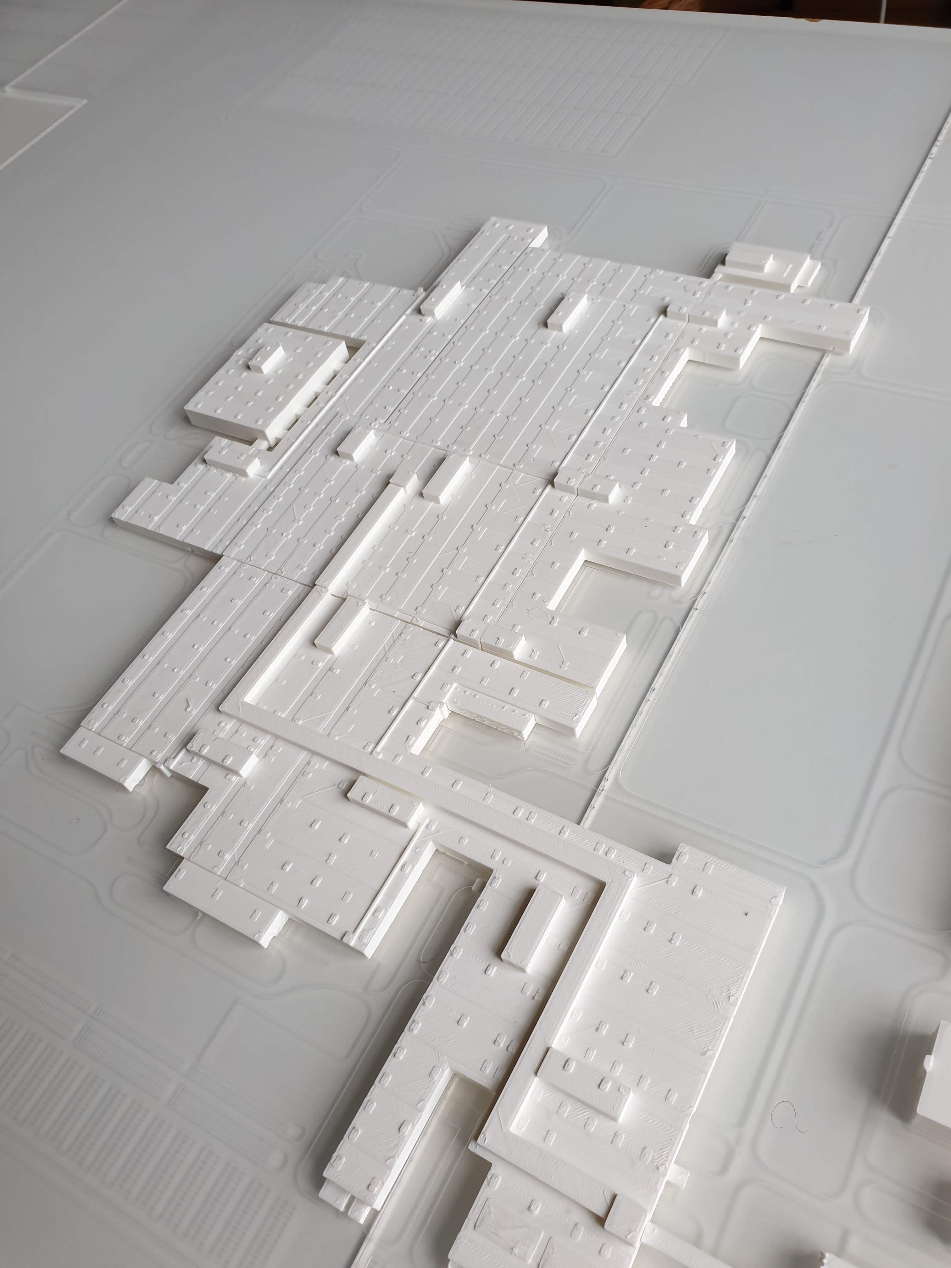
What we are talking about today – 3D printing for architecture it is… and here I will make an endorsement – I have been tinkering around with the Anycubic Chiron for quite a while.
At first after unboxing it worked great, after a while I got the infamous “T0 Senser abnormal” message mid print. Well, next to the misspelling, I had no idea.
He walked me through all the steps getting the printer functional again and right now – it’s alive and … printing..
I personally – and being part of the LRCZ team – do such endorsements not easily but Anycubic is really trying it’s best – cost is OK, support is just more than OK.
Dear congregation, let us… do something practical, I’d like to share the very essence of this year’s work at Livingroomcraftz with you:
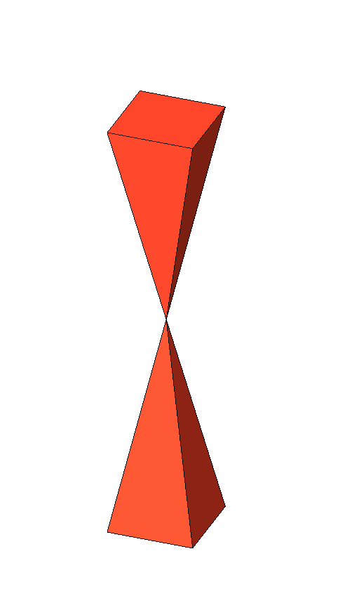
The IFC Coordination body that we all should have in our files and templates at 0,0,0 Project Origin
Not a big one you would think but in reality… and if you want to make my life as a practical BIM Manager dealing with Gigabytes of IFC files on a daily basis – pretty please..
Such as here:
It makes life just easy – welcome 2020 with this little bugger in all our files
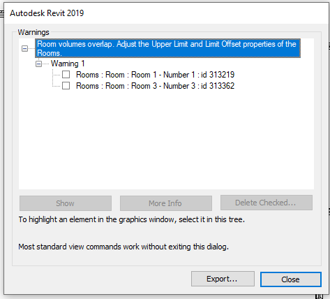
Some interesting find – don’t you love this warning in Revit:
If you are plagued by this particular warning and could validate that there is nothing overlapping..
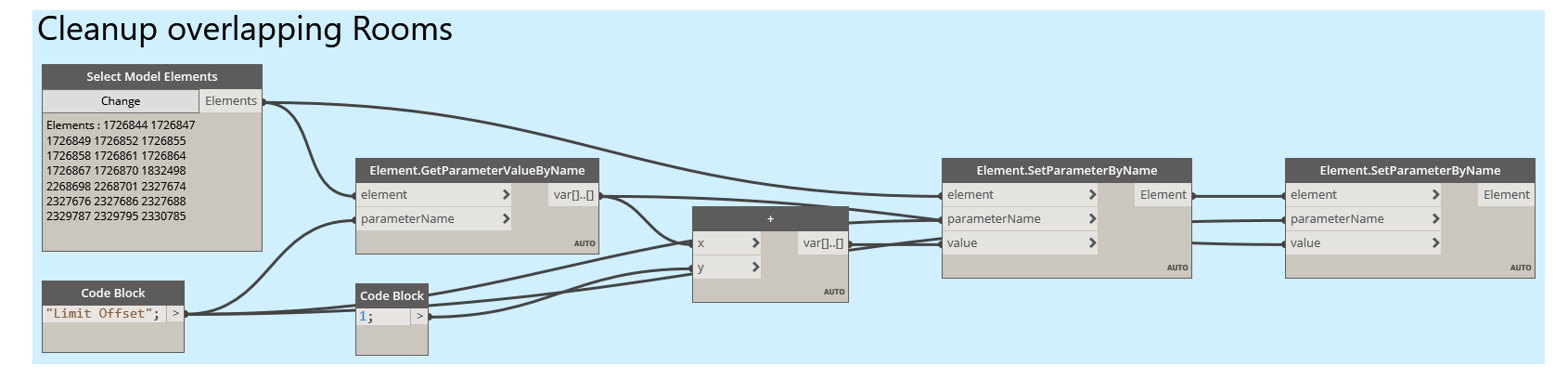
Dynamo to the rescure…
Super easy – record the Limit Offset parameter of all views, increment it and decrement it to the original value and all those stupid warnings are gone and…
Life is good – again
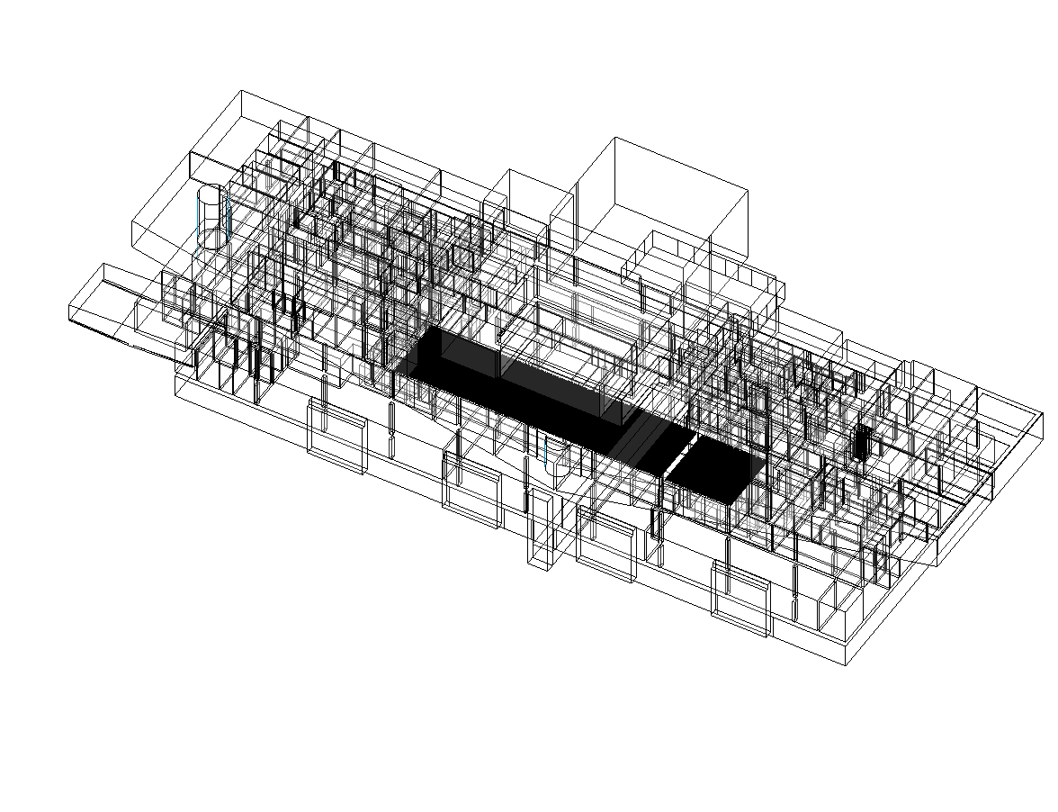
P.S.: How to make rooms visible in a 3D View is another story – stay tuned….